


 Abstract
 HTML
HTML Reference
 Related
 PDF
PDF


-
The low-energy heavy-ion storage ring CRYRING [1] was originally located at the Manne-Siegbahn Laboratory in Stockholm, Sweden, where experiments including electron-ion collision with multiply charged atomic ions were conducted [2]. The ion species with the highest charge state stored in CRYRING was Pb54+ [3], which was provided by a cryogenic electron-beam ion source, leading to the name CRYRING. In 2013, CRYRING was transferred to Darmstadt, Germany, as a Swedish in-kind contribution to the international Facility for Antiproton and Ion Research (FAIR). At its new location, the ring was coupled with the heavy-ion accelerator complex of the GSI Helmholtz Center for Heavy-Ion Research consisting of the universal linear accelerator (UNILAC), the heavy-ion synchrotron SIS18, and the experimental storage ring ESR, thereby becoming CRYRING@ESR.
The GSI accelerator complex is capable of delivering intense beams of heavy ions with the highest charge states to CRYRING@ESR (e.g. Pb82+ [4]), facilitating a unique research program in atomic, nuclear and fundamental physics [5]. Part of the research program addresses electron-ion collision spectroscopy of highly-charged heavy ions, which the aim of testing strong-field quantum electrodynamics (QED) with highest precision. Electron-ion collision spectroscopy exploits resonance features that occur in the cross sections of atomic processes, such as electron-impact ionization of ions or electron-ion recombination [6].
Recently, we reported the first results on resonant electron-ion recombination of berylliumlike Pb78+ ions [7], with the experimental uncertainty lower than that predicted by theory [8], thus constraining the second order strong-field QED contributions to
$ 2s\to2p $ core excitation energies. In the present paper, we provide a detailed description of the experimental and data analysis procedures pertaining to electron-ion collision spectroscopy at CRYRING@ESR along with further results for Pb78+. -
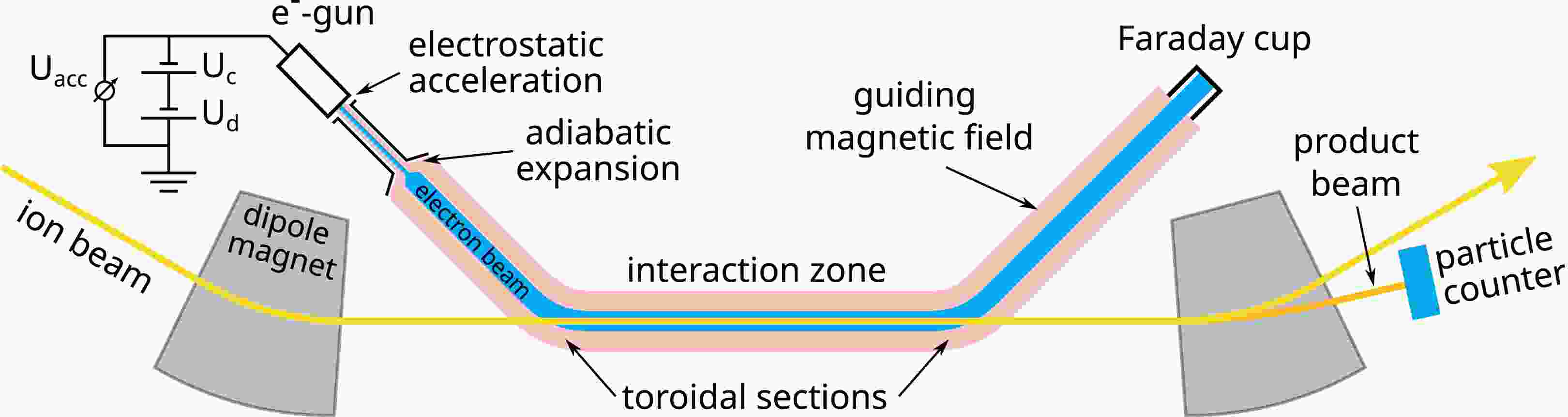
Electron-ion collision spectroscopy at CRYRING@ESR employs the ultra-cold electron beam of its electron cooler [9−12] as an electron target for electron-ion recombination. A sketch of the experimental electron-ion merged-beams arrangement is provided in Fig. 1. In the electron cooler, the electron beam is magnetically guided onto the ion orbit such that electrons and ions move coaxially in the same direction. Recombined product ions have a lower charge than the stored primary ions and therefore leave the closed orbit at the first dipole magnet downstream of the electron cooler. The recombined ions are counted by an appropriately placed single-particle detector (for details see [13]).
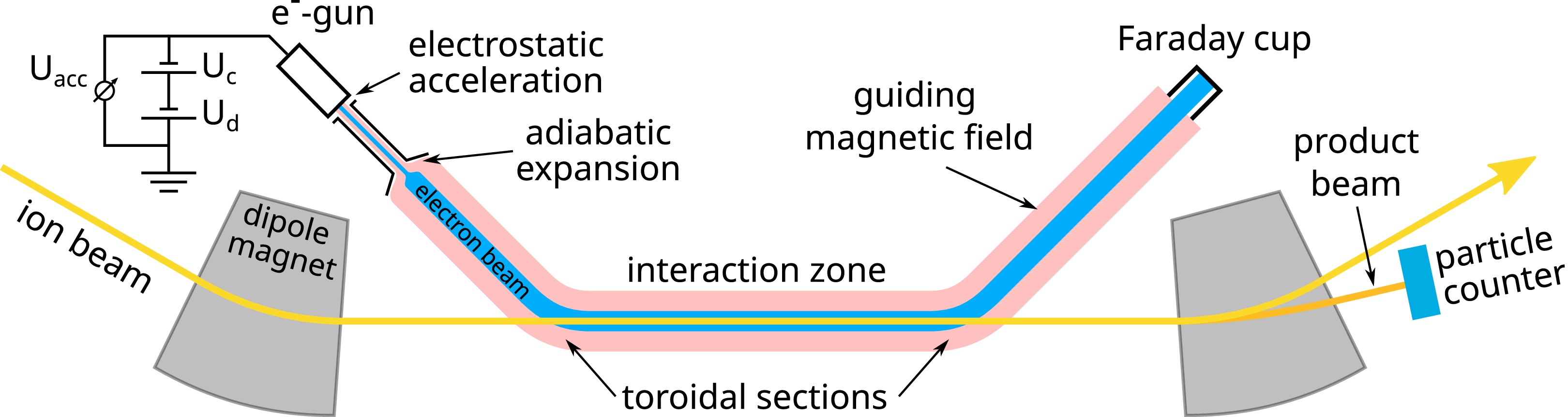
Figure 1. (color online) Schematic of the experimental arrangement for electron-ion collision spectroscopy at the CRYRING@ESR electron cooler, which is located in one of the twelve straight sections of the storage ring.
Electron cooling forces the velocity
$ v_i $ of ion beam towards the average electron beam velocity$ v_e $ and leads to a decrease of the ion-beam diameter and its internal velocity spread [10, 14]. The electron energy, at which the cooling condition, i.e.$ v_i=v_e $ , is realized, is referred to as the cooling energy,$ E_\mathrm{cool} $ . In electron-ion collision spectroscopy, recombined ions are counted as a function of the electron-ion collision energy. The latter is varied on a millisecond time scale by changing the electron cooler's cathode voltage, as explained in more detail in Sec. II.A below.Since the aim of electron-ion collision spectroscopy is to accurately map recombination resonances [15−17] an energy spread,
$ \delta E_\mathrm{cm} $ , of the electron beam that is as low as possible in the electron-ion center-of-mass frame is of primary concern. The energy spread can be expressed as [18]$ \begin{aligned} \delta E_\mathrm{cm} = \sqrt{(kT_\perp\ln2)^2+16E_\mathrm{cm}kT_\|\ln2}\; , \end{aligned} $

(1) where k is the Boltzmann's constant, and
$ T_\| $ and$ T_\perp $ denote the parallel and transverse temperatures of the electron beam, respectively, with respect to the beam propagation direction. The energy spread increases with increasing electron-ion center-of-mass energy$ E_\mathrm{cm} $ . Therefore, ions which exhibit recombination resonances close to$ E_\mathrm{cm}=0 $ eV are particularly suited for electron-ion collision spectroscopy studies. In the CRYRING@ESR electron cooler, the transverse temperature is determined by the electron gun's cathode temperature,$ T_\mathrm{cath} $ , and the beam expansion factor,$ \chi=B_\mathrm {cath}/B $ , which is realized by passing the electron beam from a region of initially high magnetic guiding field$ B_\mathrm{cath} $ generated by a superconducting solenoid to a region of lower field B (Fig. 1). The maximum value for the beam expansion factor is 100. As the acceleration of the electron beam in the longitudinal direction,$ T_\| $ is usually much lower than$ T_\perp $ . At CRYRING,$ kT_\perp = kT_\mathrm{cath}/\chi = 100\mathrm{\; meV}/100 = 1 $ meV and$ kT_\| = 0.08 $ meV are expected [3]. Fig. 2 shows that resonances at energies below ~10 eV benefit immensely from the ultra-cold electron beam at CRYRING@ESR compared with the conditions at the ESR electron cooler.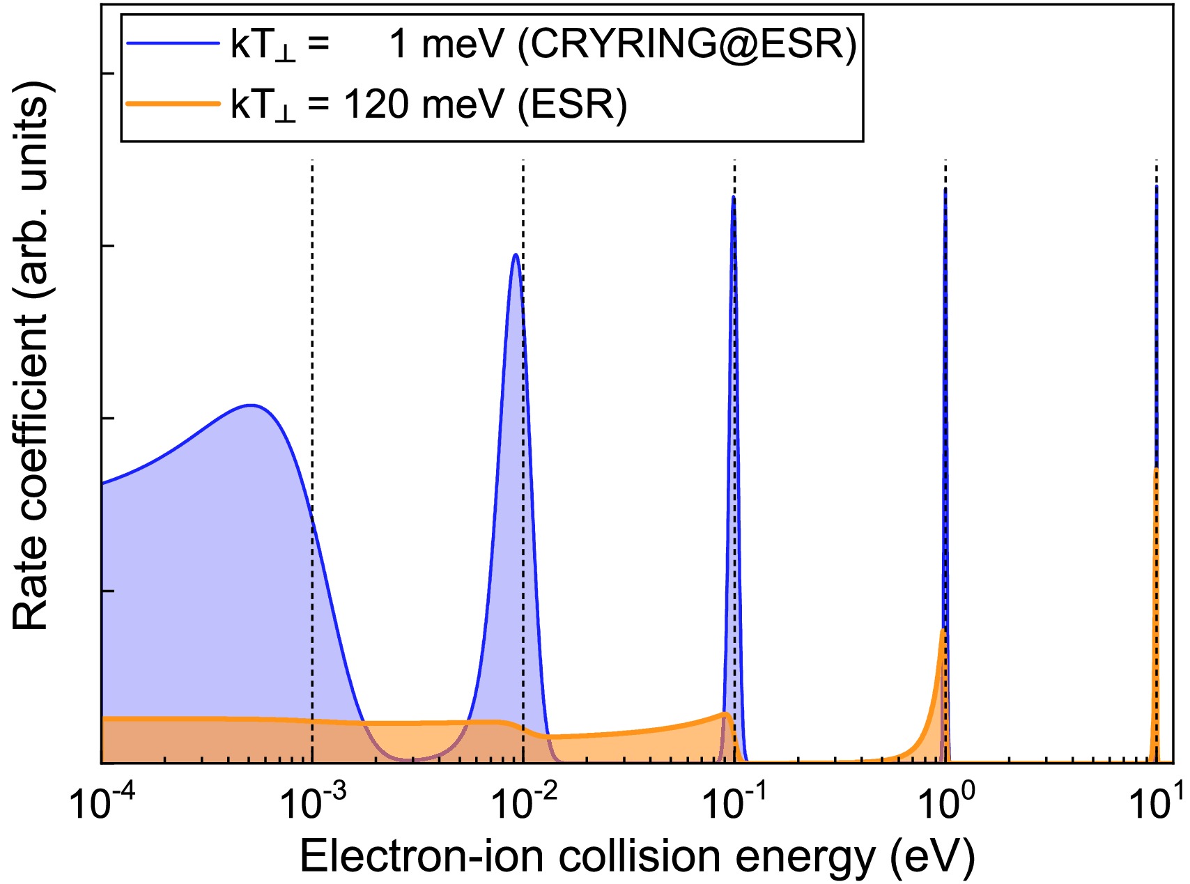
Figure 2. (color online) Synthetic recombination spectra with delta-like resonances at the indicated positions (dashed vertical lines). The shaded curves result from the convolutions of the resonances with the cooler electron energy distributions at the heavy-ion storage rings CRYRING@ESR (blue curve,
$ kT_\perp= $ 1 meV,$ kT_\| = $ 0.1 meV) and ESR (orange curve,$ kT_\perp= $ 120 meV,$ kT_\| = $ 0.1 meV). The immense gain in resolving power of CRYRING@ESR with respect to ESR is obvious. -
The electron energy in the laboratory frame is determined by the electron cooler's cathode voltage which corresponds to the electrons' acceleration voltage,
$ U_\mathrm{acc} = U_c+U_d $ , and is generated by two high-voltage supplies in series (Fig. 1). A slow high-voltage supply delivers the voltage$ U_c $ , which is set such that the cooling energy$ E_\mathrm{cool} $ is realized. A fast high-voltage amplifier (Kepco BOP 1000M) provides the detuning voltage$ U_d $ , which is varied during measurements while keeping$ U_c $ constant. The input voltage of the high-voltage amplifier is generated by a 20-bit digital-to-analog converter (DAC) (Analog Devices AD5791), which is controlled by a microcontroller (Teensy 3.6). The latter is connected via USB to a Linux computer (Raspberry Pi 4), which can be accessed via the local network. Before the start of a recombination measurement, the 'ramp file' which is an ascii file containing the sequence of voltage values (Fig. 3), is consecutively set during a voltage ramp, along with the corresponding timing information that needs to be uploaded to the microcontroller. A graphical user interface (GUI, Fig. 4) is available for the generation and upload of the ramp file to the microcontroller.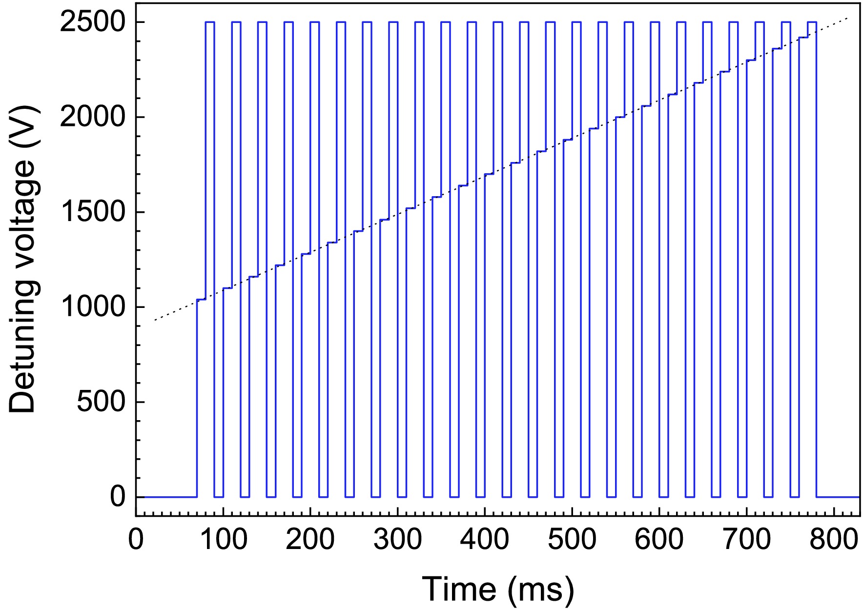
Figure 3. (color online) Example of a voltage ramp for recombination measurements. The detuning voltage is alternately switched between cooling (
$ U_d^{(c)}=0 $ V), measurement ($1000\; {\rm V} \leq $ $ U_d^{(m)}\leq 2420$ V), and reference ($ U_d^{(r)}=2500 $ V). The time duration of each voltage step is 10 ms. The dotted line is to guide the eye along the sequence of measurement voltages.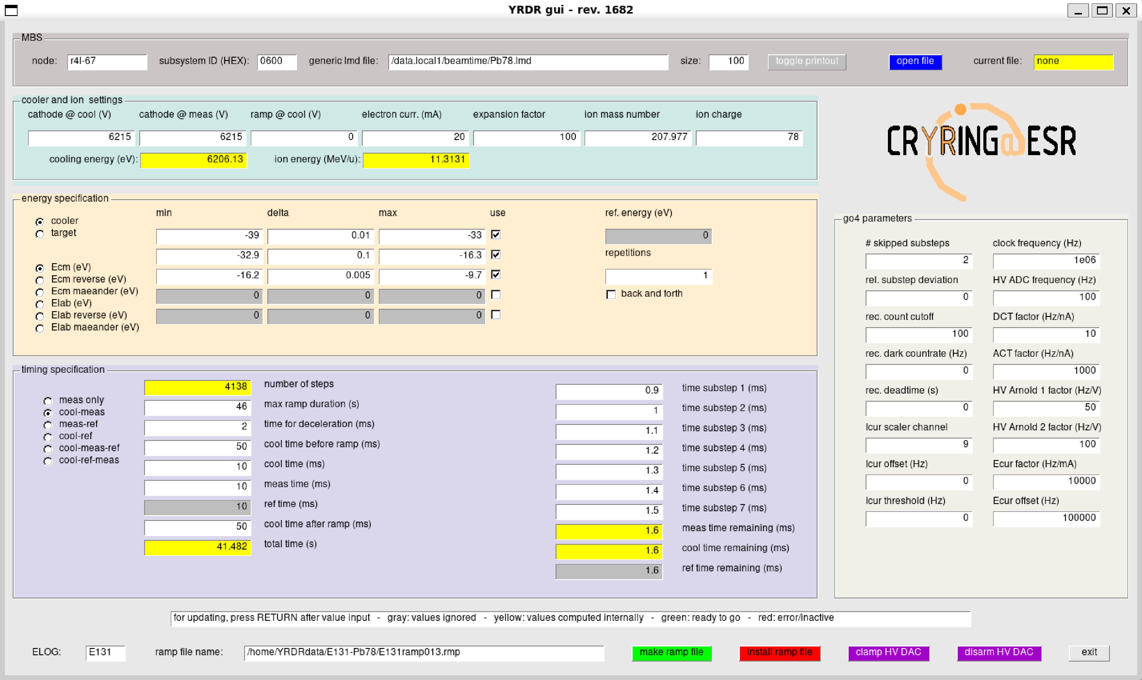
Figure 4. (color online) ROOT [19] based graphical user interface (GUI) for the control of electron-ion recombination measurements at the CRYRING@ESR cooler.
-
Precision collision spectroscopy requires accurate knowledge of the velocities of the colliding particles. To this end, the acceleration voltage
$ U_\mathrm{acc}=U_c+U_d $ of the electrons is recorded by high-voltage probes for each of the voltage steps in the voltage ramp. The high-voltage probes must be able to follow the changes of$ U_\mathrm{acc} $ , which occur on the millisecond time scale. For this purpose two fast high voltage probes were built by the Giessen and Münster groups.The Giessen device (known as 'Arnold') was developed more than two decades ago and has already been used at the ESR storage ring [20]. It is based on a commercial 200-MΩ high-voltage divider (HVT-21 by EBG Austria) with a divider ratio of 1000:1. The HVT divider is only 52 mm × 25.4 mm in size and is mounted in a closed metal cylinder. It was developed to enable a very fast high-voltage measurement with rise times of less than 40 μs when going from 10% to 90% of the requested voltage change and without any capacitive corrections. This goal was achieved by means of a stainless steel cap acting as a grading top electrode to minimize stray capacitance, that otherwise would lead to long RC times in connection with high ohmic value of the resistor chip [21]. The output voltage is fed into a temperature-stabilized (
$42\pm 0.3$ ℃) voltage-to-frequency converter (VFC, Analog Devices AD652BQ) with a maximum output frequency of 1.2 MHz.The Münster fast high-voltage probe (termed 'FC20') was designed and built particularly for use in collision-spectroscopy experiments at CRYRING@ESR and is a capacitively corrected type. In combination with a precision multimeter (Keithley DMM7510), which is used for read out, it is about an order of magnitude more precise than the Giessen device. Further technical details are provided in [22]. Previously, the Münster group built an even more precise but slower high-voltage divider ('G35') for DC voltages, which is similar to the Karlsruhe Tritium Neutrino (KATRIN) divider described in [23] and allows measurements of voltages up to 35 kV with an accuracy of a few ppm (10−6). This value includes the uncertainty of the 8.5-digits-voltmeter (Keysight 3458A DVM) that is used for readout. The G35 divider was calibrated in Münster up to 35 kV using a novel absolute calibration method [24] and later at GSI at 1 kV against a commercial precision divider (Fluke 752A). The 100:1 divider ratio has an uncertainty of 0.5 ppm when properly adjusted.
When measuring the voltage dependence of the scale factors for a voltage range of ±1 kV around the cooler base voltage, the FC20 divider was stable at the 0.5 ppm level, whereas the Arnold divider exhibited a variation of 95 ppm over a time interval of several days. When measuring fast voltage changes, as in the actual experiment, the scale factor of the FC20 divider stabilized within 2 ms in a ±10 ppm interval. The FC20 divider therefore allows an accuracy of
$ \mathcal{O}(10\; {\rm ppm}) $ whereas a measurement with the G35-calibrated Arnold device is expected to be accurate at the 100 ppm level. -
For data acquisition the GSI Multi Branch System (MBS) [25] was used. This hardware is based on the Versa Module Eurocard-bus (VME). The VME crate houses a central processing unit (CPU) with a Linux operating system that runs the MBS software. The data acquisition is event based, where each event is signaled by a trigger. The triggers are generated by the accelerator hardware (trigger 'Injection'), the microcontroller that controls the high-voltage amplifier (triggers 'New Ramp' 'New Voltage', 'End of Ramp'), or a sequencer. The latter provides up to seven subtriggers for each voltage step. These subtriggers occur after each 'New Voltage' trigger and are separated in time by preselected time intervals. The subtrigger timing sequence can be defined as in the above mentioned GUI (time substeps 1–7 in Fig. 4). The timing sequence is transferred to the sequencer via a dedicated Linux computer (Raspberry Pi 4) concurrently uploadng a ramp file (Sec. II.A).
All trigger signals are fed into a GSI-developed trigger module (GSI TRIVA), which is located in the VME crate. When the trigger module receives a trigger it passes a trigger-characteristic bit pattern to the MBS and initiates a readout of the VME scalers (GSI VULOM), which collect the data from the various measurement devices (detectors, volt meters, and ampère meters), most of which are interfaced by VFCs. Another module (GSI VETAR) provides a 'White Rabbit' [26] time stamp for each event, which can be used in the offline analysis for synchronizing data streams from different MBS systems with sub-nanosecond accuracy.
The data packages that are generated by each event consist of a header, a time stamp, an identification of the trigger, and the contents of the scaler channels. The data packages are written consecutively to a file that is linked to the MBS output data stream. During an experiment, this data stream is also directed to online data-analysis code to visualize the measured data and derive quantities such as the measured recombination rate coefficient (Sec. III.C). This code is embedded in the GSI software Go4 [27], which provides convenient access to the MBS data structures. The same code is also used for the refined processing of the data files in subsequent offline data analysis.
-
The essential aspect of electron-ion collision spectroscopy at CRYRING@ESR is an as-accurate-as-possible determination of the electron-ion collision energy, which requires a careful analysis of all the associated uncertainties. The electron-ion collision energy in the center-of-mass frame can be expressed in terms of the laboratory electron and ion velocities
$ v_e $ and$ v_i $ , respectively, and the angle θ between the two interacting beams as [20]$ \begin{aligned} E_{\mathrm{cm}} = m_ic^{2} (1 + \mu) \left[ \sqrt{1 + \frac{2\mu(\gamma_\mathrm{rel} - 1)}{(1 + \mu)^{2}} } - 1 \right], \end{aligned} $

(2) where c is the speed of light in vacuum;
$ \mu=m_e/m_i\ll1 $ is the ratio of the electron rest mass$ m_e $ to the ion rest mass$ m_i $ and$ \begin{aligned} \gamma_\mathrm{rel} = \gamma_{e}\gamma_{i}\left(1 - \beta_e\beta_i\cos\theta\right) \end{aligned} $

(3) with
$ \beta_e =v_e/c $ ,$ \beta_i=v_i/c $ ,$ \gamma_e=(1-\beta_e^2)^{-1/2} $ , and$\gamma_i= (1-\beta_i^2)^{-1/2}$ . For the electron-cooling condition, i.e., for$ \theta=0 $ and$ v_i=v_e $ , Eqs. (3) and (2) yield$ \gamma_\mathrm{rel} = 1 $ and$ E_\mathrm{cm}=0 $ , respectively, as expected. The associated electron energy is the cooling energy,$ E_\mathrm{cool} $ , which is related to$ v_i $ via$ \gamma_i = [1-(v_i/c)^2]^{-1/2} = 1 + E_\mathrm{cool}/(m_ec^2) $ . When the electron energy is detuned relative to the cooling energy by an amount$ E_d $ this results in$ E_e=E_\mathrm{cool}+E_d $ and$ \gamma_e = 1 + E_e/(m_ec^2) $ . The electron-ion collision energy, thus, depends on$ E_\mathrm{cool} $ ,$ E_d $ , and θ. Consequently its uncertainty can be estimated from the uncertainties$ \Delta E_\mathrm{cool} $ ,$ \Delta E_d $ , and$ \Delta \theta $ as$ \begin{aligned}[b] (\Delta E_\mathrm{cm})^2 =\;& \left\vert\frac{\partial E_\mathrm{cm}}{\partial E_\mathrm{cool}}\right\vert^2_{\theta=0}(\Delta E_\mathrm{cool})^2 + \left\vert\frac{\partial E_\mathrm{cm}}{\partial E_d}\right\vert^2_{\theta=0}(\Delta E_d)^2 \\ +& \left\vert\frac{1}{2}\frac{\partial^2 E_\mathrm{cm}}{\partial \theta^2}\right\vert^2_{\theta=0}(\Delta \theta)^4 =\; \frac{1}{1+2\mu\gamma_\mathrm{rel}+\mu^2} \\ &\times \left\{\left\vert\gamma_i\left(1-\frac{\beta_i}{\beta_e}\right)+ \gamma_e\left(1-\frac{\beta_e}{\beta_i}\right)\right\vert^2(\Delta E_\mathrm{cool})^2\right. \\ &+ \left\vert\gamma_i \left(1-\frac{\beta_i}{\beta_e}\right)\right\vert^2(\Delta E_d)^2\\ &+ \left.\left\vert \frac{\gamma_e\gamma_i\beta_e\beta_i}{2}\right\vert^2\left[m_ec^2(\Delta \theta)^2\right]^2\right\}. \end{aligned} $

(4) Since
$ \partial E_\mathrm{cm}/\partial\theta \propto\sin\theta $ vanishes for$ \theta=0 $ , the second-order term of the Taylor expansion is used to account for$ \Delta \theta $ . Fig. 5 shows an estimate of$ \Delta E_\mathrm{cm} $ based on reasonable assumptions for the underlying systematic uncertainties [7]. At electron-ion collision energies below 1 eV,$ \Delta E_\mathrm{cm} $ is smaller than 1 meV.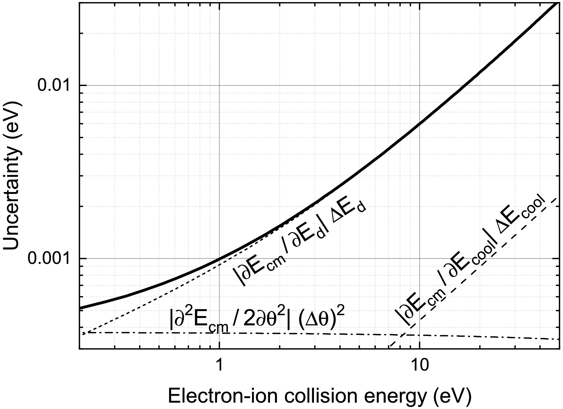
Figure 5. Uncertainty of the experimental energy scale and individual contributions according to Eq. (4) for
$ E_\mathrm{cool}=6000 $ eV,$ m_i = 238 $ u,$ \Delta E_d/E_d=10^{-5} $ ,$ \Delta E_\mathrm{cool} = 0.25 $ eV,$ \Delta \theta = 0.25 $ mrad. -
The electron energy is determined not only by the voltages
$ U_c $ and$ U_d $ of the cathode and detuning supplies, respectively, but also by the space-charge potential,$ U_\mathrm{sc} $ , of the electron beam, i.e.,$ \begin{aligned} E_e = E_\mathrm{cool}+E_d = -e(U_c+U_d) + eU_\mathrm{sc}. \end{aligned} $

(5) Here
$ U_\mathrm{sc} $ depends on the radial position in the cylindrical electron beam with radius$ r_e = r_c\sqrt{\chi} $ , and$ r_c= 0.2 $ cm is the radius of the electron coolers' cathode.$ U_\mathrm{sc} $ reaches its minimum on the beam axis and is expressed as [28]$ \begin{aligned} U_\mathrm{sc} = -\frac{1}{4\pi\varepsilon_0}\left(1+2\ln\frac{r_t}{r_e}\right)\frac{I_e}{v_e}, \end{aligned} $

(6) where
$ r_t=5.0 $ cm is the radius of the vacuum tube surrounding the electron beam1 and$ \varepsilon_0 $ is the vacuum electric permittivity. Note that$ U_c+U_d $ and$ U_\mathrm{sc} $ are negative, and the space-charge potential thus lowers$ E_e $ . Since the space-charge potential via$ v_e $ depends on$ E_e $ itself, it must be calculated iteratively. Usually, only few iterations are required for reaching convergence. As explained in [7], the space-charge potential contributes to$ E_\mathrm{cool} $ and$ E_d $ (Eq. (5)) and consequently to the uncertainties$ \Delta E_\mathrm{cool} $ and$ \Delta E_d $ . This was taken into consideration in the error estimate displayed in Fig. 5 [7]. -
The measured merged-beams recombination rate coefficient
$ \alpha_\mathrm{mb} $ was considered on an absolute scale (with typically ±14% systematic uncertainty [28]) by normalizing the background-subtracted detector count rate R by the number$ N_i $ of stored ions and the electron-density$ n_e $ as in [20]$ \begin{aligned} \alpha_\mathrm{mb}(E_\mathrm{cm}) = \frac{R(E_\mathrm{cm})\,C/L}{[1-\beta_e(E_\mathrm{cm})\beta_i] N_i n_e(E_\mathrm{cm}) \eta}, \end{aligned} $

(7) where
$ C = 54.178 $ m is the ring circumference;$ L= 0.9 $ m is the length of the electron cooler's straight section; and η denotes the detection efficiency of the single particle detector. The number of ions can be calculated from the ion current$ I_i $ as follows:$ \begin{aligned} N_i=\frac{I_i}{ev_i}C, \end{aligned} $

(8) where e denotes the elementary charge. The electron density is obtained from the electron current
$ I_e $ and the electron-beam cross section$ A=\pi r_e^2 $ as follows:$ \begin{aligned} n_e(E_\mathrm{cm}) = \frac{I_e}{ev_e(E_\mathrm{cm}) A}. \end{aligned} $

(9) -
Comparing the measured merged-beams rate coefficients with those of theoretical cross sections requires the latter to be convolved with the experimental electron energy distribution. This has been discussed comprehensively in the appendix of [20]. The electron energy distribution can be represented analytically as a flattened Maxwellian, which is characterized by the electron beam temperatures
$ T_\| $ and$ T_\perp $ . However, a convolution with this distribution function does not account for the effects of non-zero angles observed between electron and ion beam in the merging and demerging regions of the electron cooler, where the electrons follow the magnetic field lines of the respective toroidal magnets. This and other experimental effects (such as the almost negligible energy spread of the ion beam) can be conveniently accounted for by a Monte-Carlo convolution as described in [20] for electron-ion collision spectroscopy at the ESR electron cooler.The dependence of the angle on the position in the cooler was obtained from measurements of the magnetic field inside the electron cooler performed during commissioning in Stockholm. We combined high-precision measurements of the field homogeneity near the cooler center, as reported in [9], with lower-precision vertical field maps of the toroidal sections [29]. The result is depicted by the full symbols in Fig. 6. To facilitate the Monte-Carlo convolution, the data points were fitted by the function
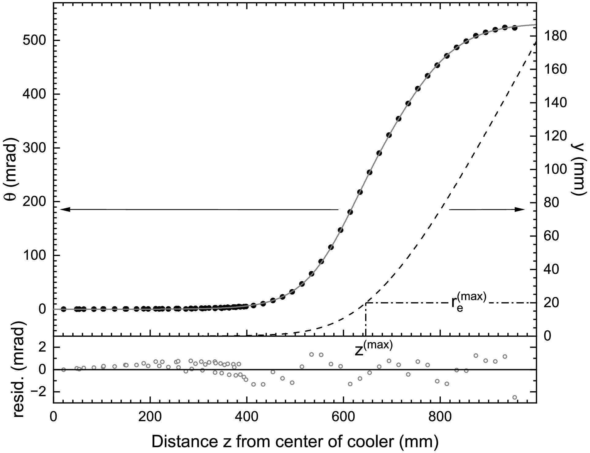
Figure 6. Upper panel: Measured angle of the magnetic field (full symbols, left scale) in the CRYRING electron cooler with respect to the cooler axis and as a function of distance z from the cooler center at
$ z=0 $ . The angle is essentially zero in the straight section of the cooler and increases in the toroidal sections (Fig. 1). The full line results from a fit of Eq. (10) to the measured data points. The fit parameters are listed in Table 1. The dashed line represents the vertical offset$ y(z) $ (right scale) as calculated from Eq. (11). The deflection that corresponds to the maximum electron-beam radius ($r_e^\mathrm{(max)}=r_c\sqrt{\chi}= $ $ 10r_c=20$ mm for the maximum expansion factor$ \chi=100 $ ) occurs at$ z^\mathrm{(max)} = 646 $ mm. Lower panel: Residuals of the fit (open symbols).$ \begin{aligned} \theta(z) &= \tilde{\theta}(|z|)-\tilde{\theta}(0)\\ \rm{with} &\;\;\;\;\;\tilde{\theta}(z) = \frac{A_1}{1+\exp\left(\dfrac{ z_1-z}{ k_1}\right)}+\frac{A_2}{1+\exp\left(\dfrac{ z_2-z}{ k_2}\right)}. \end{aligned} $

(10) The fit result is the full line in Fig. 6. The residuals of the fit are shown in the lower panel of Fig. 6. The parameter values that were obtained from the fit are listed in Table 1.
i $ A_i $ /mrad

$ z_i $ /mm

$ k_i $ /mm

1 307.03794 609.73215 52.11124 2 225.45754 745.68523 59.52064 Table 1. Parameter values obtained from the fit (Fig. 6) of Eq. (10) to the measured magnetic field in the CRYRING@ESR electron cooler.
Because of the deflection of the electron beam in the toroidal cooler sections, the vertical position of the electron beam center changes according to
$ \begin{aligned} y(z) \approx \int_{0}^{z}\theta(z')\,{\rm d}z' = A_1 y_1(z) + A_2 y_2(z), \end{aligned} $

(11) where
$ \begin{aligned} y_i(z) = z + k_i\ln\left[\frac{1+\exp\left(\dfrac{ z_i-z}{ k_i}\right)}{1+\exp\left(\dfrac{ z_i}{ k_i}\right)}\right] \end{aligned} $

(12) for
$ i=1,2 $ . When$ y(z) $ becomes larger than$ r_e=\chi r_c $ the overlap between electron beam and ion beam becomes zero (neglecting the ion beam radius). For$ \chi =100 $ the loss of beam overlap occurs at$ z^\mathrm{(max)} = 646 $ mm (Fig. 6), which represents the maximum z that has to be considered in the Monte Carlo convolution. To account for the specifics of the CRYRING@ESR cooler, the Monte Carlo code from [20] was adapted. -
The first beamtime at CRYRING@ESR with Pb78+ ions from the GSI accelerator chain was on electron-ion collision spectroscopy. It took place in March 2021 after a long shutdown of the accelerator facility to entirely renew the hardware and software of the accelerator control system. Remarkably, the new control system worked out of the box. Fig. 7 presents some key parameters of the beamtime.
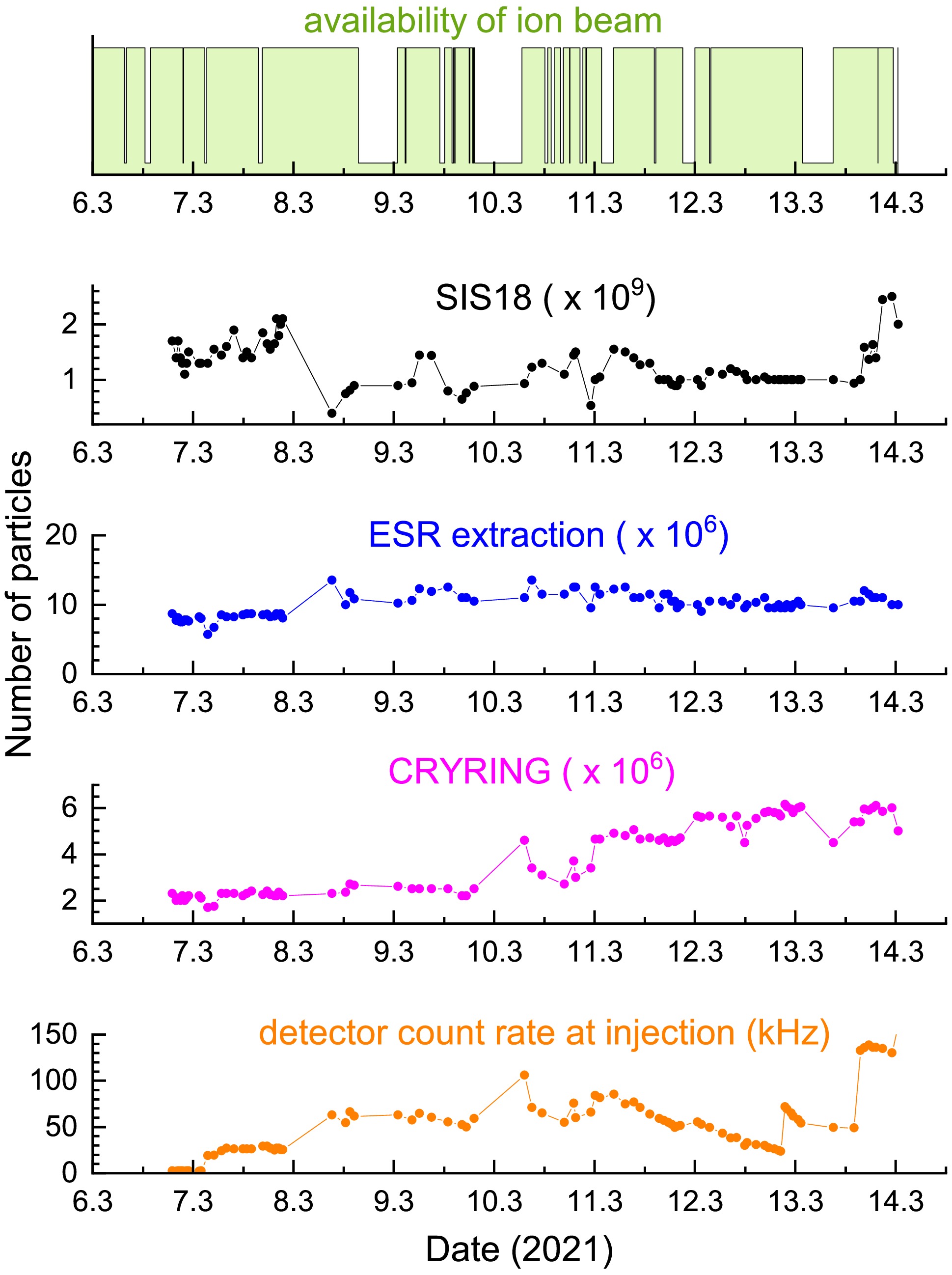
Figure 7. (color online) Beam availability, particle numbers and detector counts in the course of beamtime E131 in March 2021.
Lead ions were first accelerated by UNILAC and injected into SIS18, which further accelerated them to an energy of 54 MeV/nucleon. The desired charge state
$ q=78 $ was obtained by passing the ions through a stripper foil located in the extraction beam line of SIS18. On average,$ 10^9 $ ions per pulse were subsequently injected into ESR. There, the ions were cooled and decelerated to the final ion energy of 11.3 MeV/nucleon by operating the ESR in synchrotron mode. Eventually, up to 6 × 10⁶ 208 Pb78+ ions were injected into CRYRING@ESR. The storage lifetime of the ion beam in CRYRING@ESR was about 30 s. The detector count rate followed the number of injected ions for four days, after which detection efficiency deteriorated. This was unnoticed for some time and later remedied by increasing the detector voltages. The variation of the detection efficiency in the course of the beamtime was properly accounted for in the data analysis.The measured rate coefficient around zero electron-ion collision energy is shown in Fig. 8. Negative and positive energies indicate that the electrons have been slower and faster than the ions, respectively. The symmetry of the experimental rate coefficient around
$ E_\mathrm{cm}=0 $ eV can be exploited for an accurate determination of the cooling energy. For the current experiment this yielded$ E_\mathrm{cool}= 6197.9\pm0.2 $ eV (see [7] for details).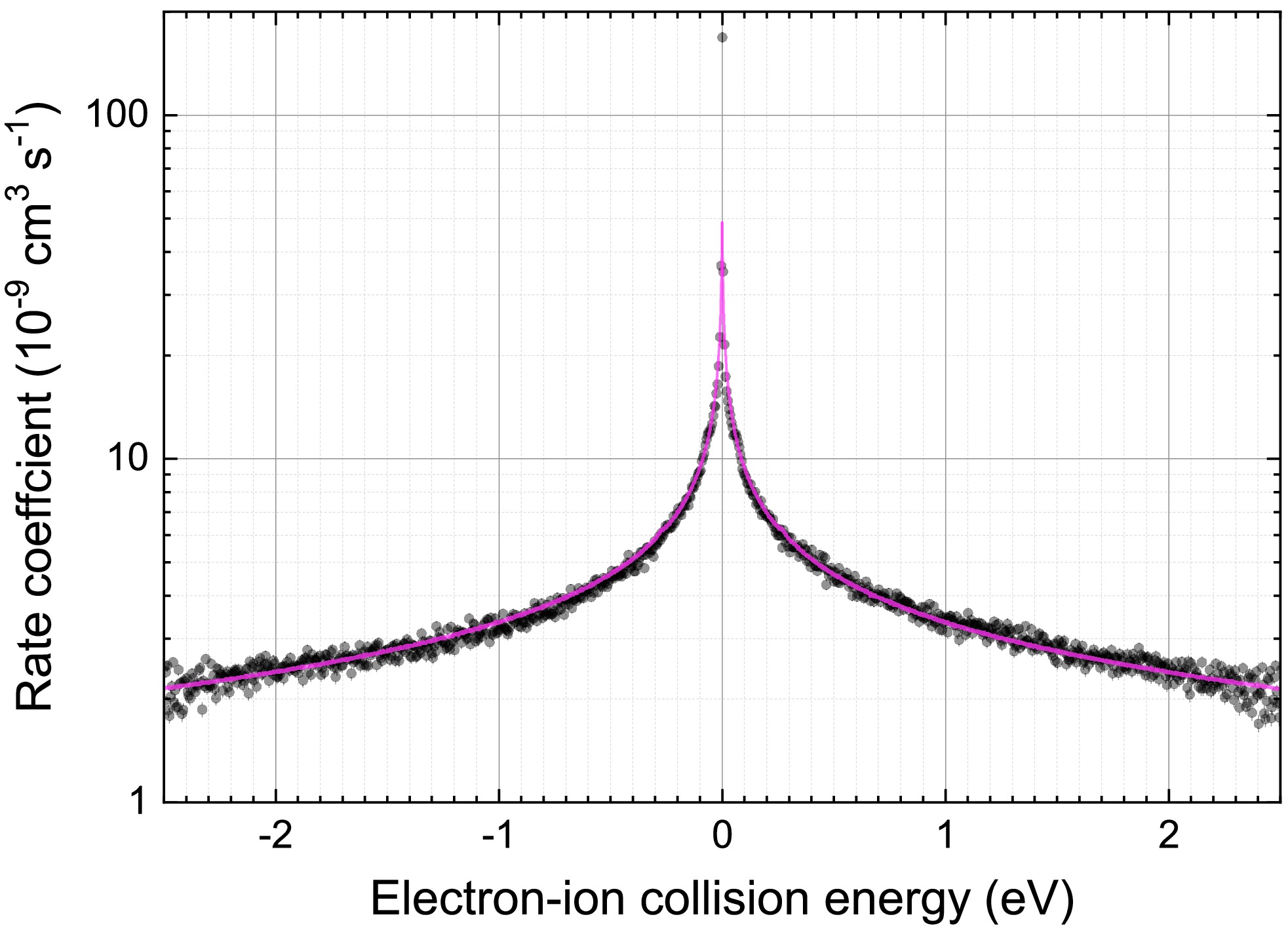
Figure 8. (color online) Measured (symbols) and calculated (full line) merged-beams rate coefficient for electron-ion recombination of Pb78+ ions in the vicinity of the RR peak at
$ E_\mathrm{cm}=0 $ . At positive (negative) energies the electrons are faster (slower) than the ions.The measured rate coefficient in Fig. 8 peaks at
$ E_\mathrm{cm}=0 $ eV because the cross section for nonresonant radiative recombination (RR) diverges at zero energy. The full line in Fig. 8 is the theoretical result for RR of Pb78+ where a semiclassical hydrogenic approximation [30, 31] has been used for the RR cross section in the Monte Carlo convolution. This approximation has been shown to be appropriate even for RR of U92+ [32], except for very low energies$ E_\mathrm{cm}\lesssim k_BT_\perp $ , where the experimental rate coefficient is larger than the theoretical one in the present case by a factor of 3.5 at$ E_\mathrm{cm} = 0 $ eV. This so called ‘recombination rate enhancement’ has been observed previously at CRYRING [33] and other storage rings [32, 34, 35] and found to be an artifact of the merged beams' arrangement at electron coolers. This intriguing phenomenon has become an attractive topic of research in itself [36−39].Results for resonant recombination of Pb78+ are presented in Fig. 9. The resonances are associated with a resonant
$ 2s\to2p $ excitation of the berylliumlike core and a simultaneous capture of the initially free electron into the$ n=19 $ Rydberg shell. The designation of the resonances is$ 2s\,2p\,(^3P_1)19\ell_j $ . Their resonance energies$ E_\mathrm{res} = E_\mathrm{exci}-E_b(n\ell_j) $ are the differences between the core-excitation energy$ E_\mathrm{exci} $ and binding energies$ E_b(19\ell_j) $ of the$ 19\ell_j $ Rydberg electron. Approximate values for$ E_\mathrm{res} $ are obtained by using the hydrogenic Dirac formula for$ E_b(19\ell_j) $ (see [17] for details) and$ E_\mathrm{exci}=244.937 $ eV [7]. The agreement with the measured resonance positions is not perfect but sufficient for their unambiguous assignment. The splittings of the$ j=1/2 $ and$ j=3/2 $ resonances is due to the interaction between the excited berylliumlike core and Rydberg electron. At higher j values the splitting is too small to be discernible at the given experimental resolving power, which does not allow the$ j\geq 7/2 $ levels to be resolved, either.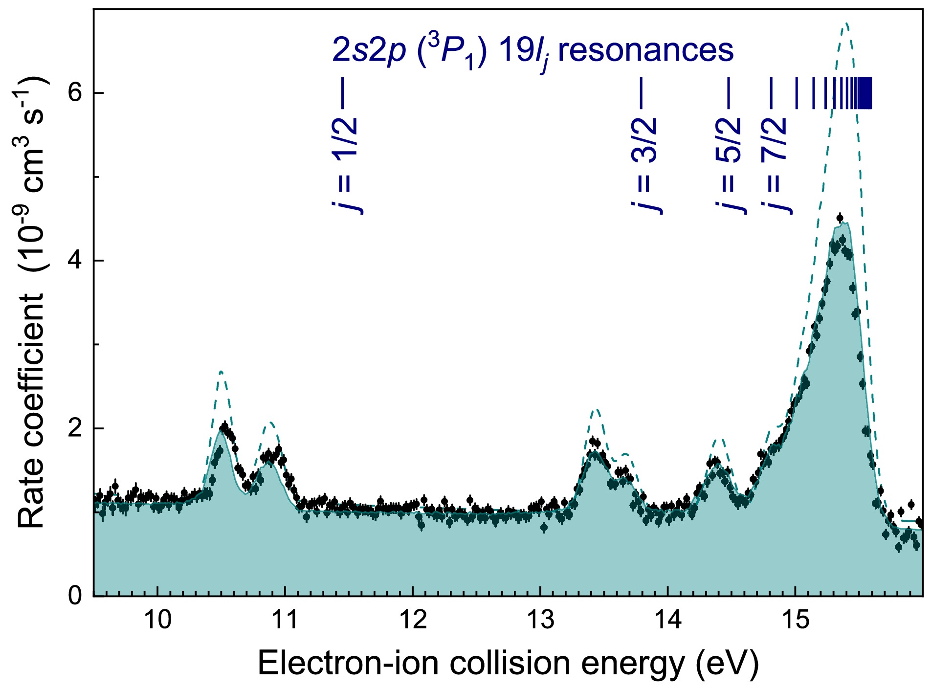
Figure 9. (color online) Measured (symbols) and calculated (shaded curve) merged-beams rate coefficient for electron-ion recombination of Pb78+ ions in the energy range of the
$ 2s\,2p\,(^3P_1)\,19\ell_j $ resonances associated with$ 2s\to2p $ core excitations. The theoretical cross sections were obtained from the JAC atomic structure code [40] and convolved by the Monte-Carlo code discussed in section 3.4. The dashed line is the result of a convolution which disregards the toroidal effects in the electron cooler. For the comparisons an overall shift of 0.34 eV was applied to all theoretical resonance positions. The vertical bars mark the positions of the individual j resonances obtained from the Dirac formula for hydrogenic ions for the$ 19\ell_j $ Rydberg binding energies (see text).The shaded curve in Fig. 9 is the result of a fully relativistic calculation using the code in the Jena Atomic Calculator (JAC) [40]. The theoretical cross section was convolved with the above mentioned Monte Carlo code (Sec. III.D). In the convolution, the electron beam temperatures
$ kT_\| = 0.23 $ meV and$ kT_\perp = 3.3 $ meV were used. The latter value corresponds to what is expected from the experimental electron beam expansion factor$ \chi = 33 $ . The parallel temperature is approximately twice larger than what was observed in earlier measurements at the CRYRING cooler. One of the reasons for this discrepancy is probably a larger-than-expected slew rate which is exhibited by the electron beam acceleration voltage upon voltage jumps of the HV amplifier [12].Apart from an overall energy shift of 0.34 eV, the agreement between the experiment and JAC calculation was excellent when the toroidal effects in the electron cooler (Fig. 6) were accounted by the Monte Carlo convolution of the theoretical cross section (shaded curve in Fig. 9). The nonzero angles
$ \theta>0 $ in the toroidal cooler sections lead to electron-ion collision energies (see Eqs. (2) and (3)) that deviate from the nominal ones realized in the straight electron-ion interaction zone (Fig. 1) where$ \theta=0 $ . This results in a smearing out of the double resonance (DR) strengths over a wide range of energies beyond the energy range of Fig. 9. Conversely, significant differences exist between experiment and theory when the toroidal effects are neglected (dashed curve in Fig. 9).The above mentioned 0.34-eV energy shift is required because decisive QED contributions are not (yet) treated by the JAC calculations [40]. Second order QED contributions to electron binding energies in berylliumlike ions have been evaluated only recently [8]. When these are accounted for there will be excellent agreement between theoretical and experimental Pb78+ recombination resonance positions. A thorough discussion on how the experiment constrains the second-order QED calculations is out of the scope of the present paper. Accordingly, the reader is referred to another, more focused publication [7].
-
Electron-ion collision spectroscopy can be successfully performed at CRYRING@ESR. Even in the very first experiment, the resonance positions can be determined to within 30 meV uncertainty (as shown in [7]), which is less than the uncertainty of very recent relevant state-of-the-art calculations employing strong-field QED to second order [8].
Since the Pb78+ beamtime, much effort has been made to improve the experimental conditions for electron-ion collision spectroscopy at CRYRING@ESR. The measures taken include providing more accurate high-voltage probes (cf. Sec. II.B; in March 2021 only the Arnold HV probe was available). In addition, a new drift tube inside the electron cooler [12] would allow faster voltage jumps compared with the variation of the potential of the full cooler terminal with much higher capacity. Meanwhile, the CRYRING@ESR vacuum can also be considerably improved. In future experiments, this will lead to longer beam storage times and less background from ion collisions with residual-gas particles.
We expect that in future experiments, the uncertainty of the experimental energy scale can be reduced by an order of magnitude compared to the Pb78+ experiment. Data from a follow-up beamtime in March 2024 with berylliumlike Au75+ ions are currently being analyzed. A new experiment proposal for an experiment with berylliumlike U88+ ions has recently been submitted to the GSI Program Advisory Committee. Theoretical calculations suggest that this ion supports strong recombination resonances in the 1–2 eV collision-energy range, where the experimental energy uncertainty is estimated to be at the meV level (Fig. 5). This would allow exploration of strong-field QED calculations beyond the second order.
-
The results presented here are based on the experiment E131, which was performed at the heavy-ion storage ring CRYING@ESR at the GSI Helmholtzzentrum für Schwerionenforschung, Darmstadt (Germany) as part of FAIR Phase-0.
Electron-ion collision spectroscopy at the CRYRING@ESR electron cooler
- Received Date: 2025-02-07
- Available Online: 2025-06-15
Abstract: Electron-ion collision spectroscopy at heavy-ion storage rings aims at precision measurements of resonance features that occur in the cross sections of electron collision processes such as electron-impact ionization of ions or electron-ion recombination. As part of the international Facility for Antiproton and Ion Research (FAIR) project, the low-energy ion storage ring CRYRING@ESR has been coupled with the heavy-ion accelerators operated by the GSI Helmholtz Center for Heavy-Ion Research in Darmstadt, Germany. This has created a new opportunity for stringent strong field quantum electrodynamics tests through electron-ion collision spectroscopy of heavy few-electron ions. The present contribution provides details of the electron-ion collision spectroscopy setup at CRYRING@ESR and associated data-analysis procedures along with first results for nonresonant and resonant recombination of berylliumlike lead ions. A recombination rate enhancement factor of 3.5 was observed for nonresonant recombination at zero electron-ion collision energy. For resonant recombination excellent agreement with recent theoretical results was obtained when these were shifted by 340 meV in energy.


 DownLoad: